Contents
Fire alarm interface documentation – Web Portal, Smart biometric clock (T2) Firmware and Hardware

Introduction
This guide explains how to set up your various systems to ensure your fire alarm interface works seamlessly with Smart biometric clock (T2) and T&A.
Pre-Requisites
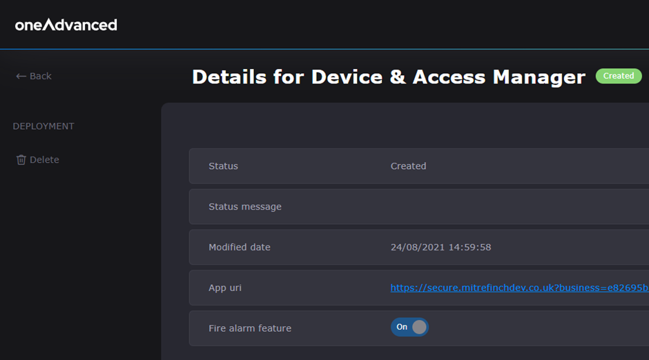
Before installing People Connect version 20250117, the Fire Alarm Interface feature must be enabled in Account maintenance.
Smart biometric clock (T2) requirements:
· Smart biometric clock (T2) must be version 2 or later,
· An access control backboard must be installed, Note: Revision B or earlier must be powered from an external 12V power supply,
Time & Attendance requirements:
· Time & Attendance installation will require an Access Control licence,
· Alarm codes will need to have been setup in Time & Attendance,
· Poller will need to have been setup in Time & Attendance,
PeopleConnect
Install the latest version of PeopleConnect, or upgrade it to version 20250117.
Once the new version of People Connect is started an urgent Service bus subscription will be created for the business.
T&A Set up
Site planner/Terminal parameters/Onsite reports
Check that the Onsite report is set up for the appropriate sites.
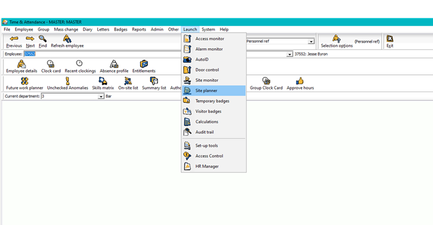
Figure 1: Access the site planner via the Time & Attendance ‘Launch’ menu
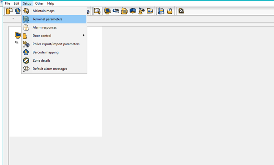
Figure 2: Select Terminal parameters from the Setup menu
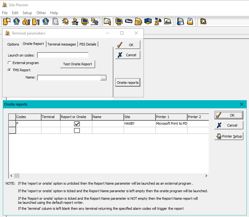
Figure 3: Onsite report options from the Terminal Parameters in Time & Attendance
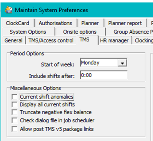
Maintain system preferences/Time & Attendance
Check that the checkbox for Check dialog file in job scheduler has not been ticked. If this option is unticked, it will read the job scheduler table entry rather than any files created in the Time & Attendance (TMS) data directory.
Hardware set up
Wire up the Fire Alarm Interface according to the following table:
Fire Alarm Interface | Smart biometric clock (T2) Access Control Backboard |
Trigger | DI1 |
Reset | DI2 |
12V | 12V Out |
Gnd | Gnd |
Then take a normally-open volt-free relay connection from the fire alarm panel and wire it to the connector labelled Fire Alarm (Conn4) in the Fire Alarm Interface.
Ensure the access control backboard is connected to the Smart biometric clock (T2) via the ribbon cable before installing the Smart biometric clock (T2) onto its bracket. Please refer to the installation guide for more details on installation.
Terminal Set up
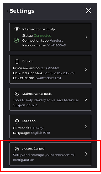
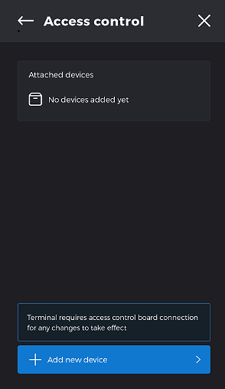
Log into the terminal and select Access Control from the settings menu to see all the devices that have been attached to the terminal.
Select Add new device
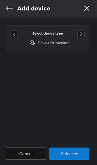
A carousel of devices will be available, choose the Fire Alarm Interface and press select.
Select the select option
The default codes for the Trigger and Reset alarm codes are F and R. Ensure these codes match the ones setup in T&A for your business.
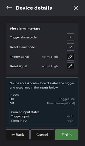
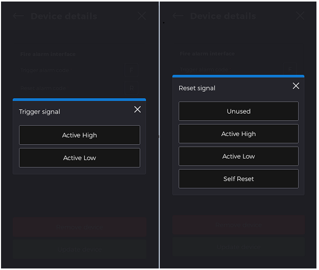
The Trigger and Reset signal should match the hardware configuration. The signals can be edited by selecting the pencil icon and selecting from the list displayed. For the Mitrefinch Fire Alarm Interface, “Active Low” should be selected.
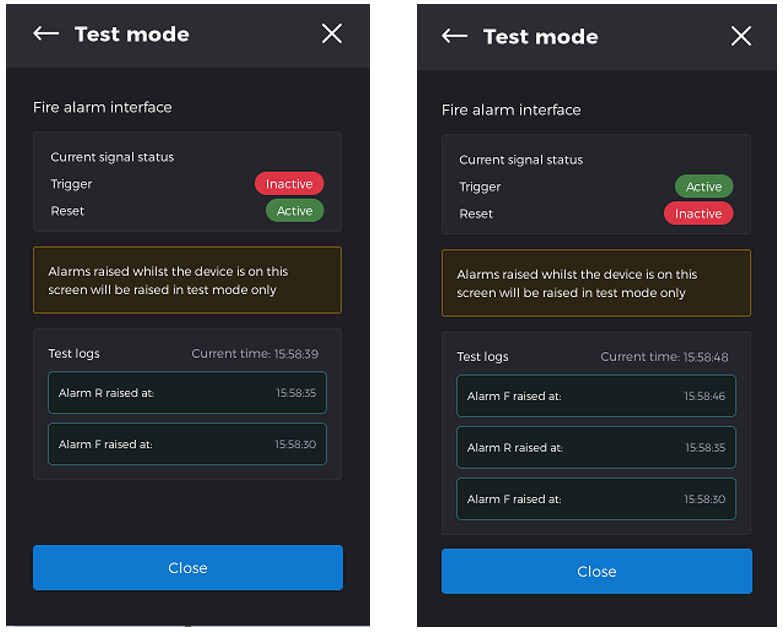
When you select Finish you have the option to Start test mode.
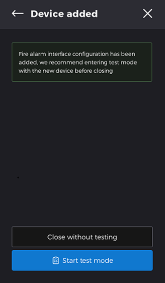
The Test Mode will raise alarms that are only displayed on the Test Mode screen. Check the Test Logs section to ensure those alarms have been raised at the correct time.
If you find any discrepancies, then adjust the Alarm code and Trigger signals as required and retest until successful.
Web Portal
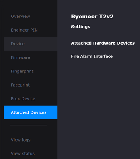
In the Portal ensure that the terminal linked to the Fire alarm system has the Fire Alarm Interface in attached devices.